


vRTCam User Guide
he vRTCam from SGBotic is designed for use with a mobile phone as remote controller with minimum setup. It turns the web browser on your mobile phone into a remote controller. No installation of Apps is required. The vRTCam will function as a wireless access point upon powered up, and uses wifi to link to your mobile phone. Each vRTCam has a unique SSID to allow multiple units to operate in close proximity.
This user guide will walk you through the technical aspect of the vRTCam. For application of this module, refer to our step-by-step guide in creating a two-wheels rover using vRTCam. The guide covers hardware assembly, wiring and Arduino programming.
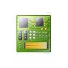
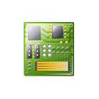
Overview & Pinout


Arduino Library & Sample Code
We have written an Arduino library to take care of the low level communication between vRTCam and Arduino board. You need to install our vRTCam library to your Arduino IDE in order to use the functions in the library. You can head over to our Github repositories to download your copy. If you're not sure on how to install the library, you may refer to this link for instructions.
Power up the vRTCam
Power the vRTCam with 5V supply. Once the vRTCam is ready, the blue STAT LED will turn from blink to solid. As the vRTCam consumes around 300mA, make sure your 5V supply is able to supply minimum 500mA (1000mA if you intend to turn on the onboard high power white LED).
As a side note, if you are using Arduino Uno board, note that the 5V pin on the Uno board is NOT able to power this module.
IMPORTANT: If the supply is insufficient to power the vRTCam, the blue STAT LED will keep blinking.
Wifi Setup
The vRTCam is designed to be a standalone Wireless Access Point (AP) upon powered up. You need to connect your mobile device's wifi to this AP in order to load the remote control panel to your web browser. Each vRTCam has its unique SSID vRTCam-xxxxxxxx where x is hexadecimal number from 0 to F. The wifi connection does not require password.
If you're not sure on how to configure the wifi, you may refer to the links below for instructions:
Remote Control Panel
Make sure your mobile device is connected to vRTCam.
Starts the web browser on your mobile device. Enter 192.168.4.1 in your web browser address bar. If the remote control panel does not load up,
- close the apps completely and try again
- ensure the blue STAT LED is not blinking
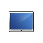
It usually takes 1~2 seconds for your web browser to be loaded with following remote control panel (the background image depends on where your vRTCam is pointing to):
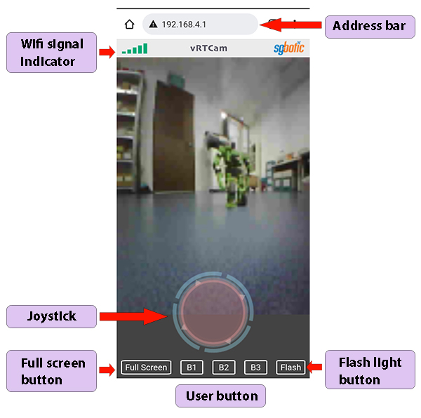
Wifi Signal Indicator: The indicator will toggle between Green (wifi connected to vRTCam) and Red (signal lost) colour. The indicator does not show the signal strength.
Joystick: This is where you control the movement of your robot. The outer blue ring will stop rotating when the orange pad is activated, or when the wifi connection is lost.
Full screen button: This button will set the remote control panel to full screen. Not all hardware supports this feature.
User button: B1, B2 and B3 are user define buttons. User can assign these buttons to perform specific tasks in their program.
Flash light button: To turn the onboard high power white LED on / off (Caution: turning this LED on will consume additional 300mA).
Serial Output
The vRTCam uses serial interface (UART) to connect to an external controller board. Only Transmit pin (Tx) is used, the Receive pin (Rx) does not implement in the firmware. For simplicity, the vRTCam uses 14-bytes fixed-length output data packet.
BaudRate
The baudrate of vRTCam output is set to 19200 bps.
Serial Packet
SSID Packet: This data packet carries the SSID information. The packet is delivered once only, when the vRTCam is ready upon powered up or reset. To receive this packet again, user needs to power cycle or reset the vRTCam.
| Byte 0 | Byte 1 | Byte 2 | Byte 3 | Byte 4 | Byte 5 | Byte 6 | Byte 7 | Byte 8 | Byte 9 | Byte 10 | Byte 11 | Byte 12 | Byte 13 |
| SYNC Char | Packet Type | SSID Byte 3 | SSID Byte 2 | SSID Byte 1 | SSID Byte 0 | X | X | X | X | X | X | X | CSUM |
- Byte 0: Sync character - 0xAA
- Byte 1: SSID packet ID - 0x04
- Byte 2 - 5: SSID of vRTCam
- Byte 6 - 12: Unimplemented
- Byte 13: Checksum
Heartbeat Packet: The heartbeat packet is to assist user in checking the wifi connection. The vRTCam will send out this heartbeat packet on a regular basis. User can use this packet to determine the wifi connection status. If you fail to receive this packet, there is a chance that the wifi connection is lost and you may need to take appropriate action (such as stopping the robot). The frequency of heartbeat packet is 5 transmission per second.
| Byte 0 | Byte 1 | Byte 2 | Byte 3 | Byte 4 | Byte 5 | Byte 6 | Byte 7 | Byte 8 | Byte 9 | Byte 10 | Byte 11 | Byte 12 | Byte 13 |
| SYNC Char | Packet Type | 1 | X | X | X | X | X | X | X | X | X | X |
CSUM
|
- Byte 0: Sync character - 0xAA
- Byte 1: Heartbeat packet ID - 0x03
- Byte 2: Fixed byte - 0x01
- Byte 3 - 12: Unimplemented
- Byte 13: Checksum
User Button Packet: This packet carries the information of the user buttons B1, B2 and B3. The output toggle when the button is activated.
| Byte 0 | Byte 1 | Byte 2 | Byte 3 | Byte 4 | Byte 5 | Byte 6 | Byte 7 | Byte 8 | Byte 9 | Byte 10 | Byte 11 | Byte 12 | Byte 13 |
| SYNC Char | Packet Type | Button B1 | Button B2 | Button B3 | X | X | X | X | X | X | X | X |
CSUM
|
- Byte 0: Sync character - 0xAA
- Byte 1: Heartbeat packet ID - 0x02
- Byte 2: Button B1 <toggle output>
- Byte 3: Button B2 <toggle output>
- Byte 4: Button B3 <toggle output>
- Byte 5 - 12: Unimplemented
- Byte 13: Checksum
Joystick Packet: This packet contains the detailed information of the joystick.
| Byte 0 | Byte 1 | Byte 2 | Byte 3 |
Byte
4 |
Byte 5 |
Byte
6 |
Byte 7 |
Byte
8 |
Byte 9 | Byte 10 | Byte 11 | Byte 12 | Byte 13 |
| SYNC Char | Packet Type | LM MSB | LM LSB | RM MSB | RM LSB | XD MSB | XD LSB | YD MSB | YD LSB | ANG MSB | ANG LSB | SP |
CSUM
|
- Byte 0: Sync character - 0xAA
- Byte 1: Joystick packet ID - 0x01
- Byte 2: Left Motor MSB (Most Significant Bit) (Byte 2 to 5: differential drive)
- Byte 3: Left Motor LSB (Least Significant Bit)
- Byte 4: Right Motor MSB
- Byte 5: Right Motor LSB
- Byte 6: X-Axis Distance from center MSB
- Byte 7: X-Axis Distance from center LSB
- Byte 8: Y-Axis Distance from center MSB
- Byte 9: Y-Axis Distance from center LSB
- Byte 10: Angle MSB
- Byte 11: Angle LSB
- Byte 12: Speed
- Byte 13: Checksum
Checksum
Here is the sample code of the checksum computing:
const unsigned char CRC7_POLY = 0x91;
unsigned char i, j, crc = 0;
  for (i = 0; i < length; i++)
  {
    crc ^= message[i];
    for (j = 0; j < 8; j++)
    {
      if (crc & 1)
        crc ^= CRC7_POLY;
      crc >>= 1;
    }
  }
