


Ultimate SR04 RGB Ultrasonic Sensor - Micro:bit Tutorial
This tutorial covers the SGBotic Ultimate SR04 RGB Ultrasonic Sensor' Micro:bit extensions and the wiring of the sensor to the Micro:bit board.
You will require an expansion board to access the I2C pin on the Micro:bit board.
All the example codes in this tutorial can be found in the "examples" folder in
our github repository.
You may refer to our User Guide for technical details of the sensor:
Installing Ultimate SR04 RGB Extensions
The Ultimate SR04 RGB comes with a MakeCode extensions that helps to simplify programming.
To install or add this extensions to your MakeCode editor, click on "Advanced" >> "Add Extensions" in the blocks category.

User the keyword "sgbotic" to search for the extension:

Alternatively you can also copy and paste the following address to the search bar and hit enter:
ttps://github.com/SGBotic/pxt-SGBotic-Ultimate-SR04-RGB
An extensions package will show up right below the search bar. Go ahead and click on it.
A "SR04-RGB" under "SGBotic" will appear in your MakeCode's block menu:
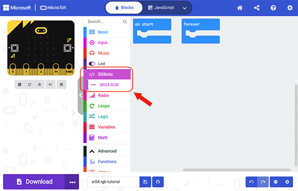
As a side note, you will need to install this extensions for every new MakeCode project that you create.
The SR04-RGB Extensions
The SR04-RGB extensions comes with two groups of almost identical blocks. The first group is to be used when you connect a single unit of Ultimate SR04 RGB to your Micro:bit. You only need to declare the I2C address once, as the blocks in this group use the declared address to communicate with the sensor.
If you are connecting multiple units of the sensor to I2C bus, and as each unit has a unique I2C address, you will have to use the blocks in the second group to communicate with each unit based on its unique address.
We will walk you through the function of each block below. Let us start with the blocks for single Ultimate SR04 RGB:
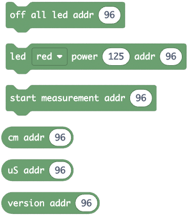
Single Ultimate SR04 RGB

This block specifies the I2C address of the Ultimate SR04 RGB. The block is pre-loaded with 96 which is the factory setting address.

To turn off all the LEDs inside the transducers.

To set the light intensity of red, green and blue LED. The value ranges from 0 to 255.

To start the distance measurement process.

Read the measured distance in centi-meters.

Read the measured distance in micro-seconds.

Read the firmware version.
Multiple Ultimate SR04 RGB
Below is the second group of blocks for multiple units of Ultimate SR04 RGB connected to I2C bus. They are almost identical to the first group except that you can address individual unit by specifying its I2C address:
Change I2C Address

The block is to change the I2C address of the Ultimate SR04 RGB. You will need to remove and re-connect the power to the unit for the change to take effect.
Wiring
Connect your Ultimate SR04 RGB to Micro:bit according to the wiring diagram below:

| Micro:bit | Ultimate SR04 RGB |
| 3V | VCC |
| 0V | GND |
| SCL (pin 19) | SCL |
| SDA (pin 20) | SDA |
This wiring applies to Ex-1 to Ex-5.
Ex-1: Read Firmware Version

This example will read and show the firmware version of Ultimate SR04 RGB on the LED matrix when button A is pressed. You need to first specify the I2C address of the sensor in the "on start" block. Click to create an arrow as shown above under "show leds" block. The arrow will point to button A to hint to user to press the button.
Ex-2: Blink LEDs

The code will change the RGB LEDs inside the transducers from red to green, then to blue and repeat the cycle continuously. The light intensity is set to highest (255).

This code is to blink the LEDs using randomly generated value to set the light intensity of red, green and blue LEDs.
Ex-3: Measure Distance (Single Unit)

The code first sends a command to Ultimate SR04 RGB to send the sound wave. Pauses for 50 mini-seconds for the sound wave to return, then reads the result from the module and shows the result on LED matrix. It waits for 200 mini-seconds before repeating the cycle again.
Ex-4: Measure Distance And Change LED color
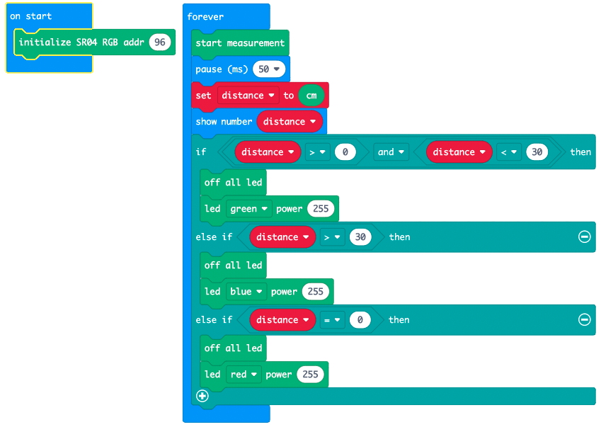
The code measures the distance of an object and changes the color of LED to
- green if the distance is less than 30cm
- blue if the distance is greater than 30cm
- red if the distance is beyond sensing range (return value of zero) which is around 4 meters.
Take note that the Ultimate SR04 RGB will return 0 if the measurement is beyond sensing range.
Ex-5: Change I2C Address

It is easy to change the I2C address of the sensor. Just place the "change I2C addr" block in the "on start" block and download to your Micro:bit. The RGB LEDs will blink four times to indicate that the I2C address has been successfully changed.
You will need to remove and re-connect the power for the change to take effect.
Reset to factory setting
To reset the I2C address back to factory setting (96, or 0x60 hexadecimal), short the SCL pin to 0V and apply power. The LED will blink three times upon successfully reset. Refer to the User Guide for details.
Ex-6: Measure Distance (Three Units)
Wiring:

Code:

The code uses three units of Ultimate SR04 RGB to measure distance of objects. The I2C address of the three units are pre-configured to 95, 96 and 97 respectively.
The code triggers the three units in sequence, delay for 50 mS and return to read back the results. The results will be shown on the LED matrix.
