


Ultimate SR04 RGB Ultrasonic Sensor - Arduino Tutorial
This tutorial covers the SGBotic Ultimate SR04 RGB Ultrasonic Sensor' Arduino library and the wiring of the sensor to the Arduino board. While the example codes can be applied to Arduino Uno, ESP32 and ESP8266, the wiring is based on the Arduino Uno board.
You need to install our Ultimate SR04 RGB library to your Arduino IDE in order to run the sketch. You can head over to our github repositories to download your copy. If you're not sure on how to install the library, you may refer to this link for instructions.
All the example codes in this tutorial can be found in the "examples" folder in our library.
You may refer to our User Guide for technical details of the sensor:
Wiring
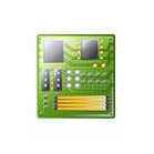
Connect your Ultimate SR04 RGB to the Arduino Uno according to the wiring diagram below:
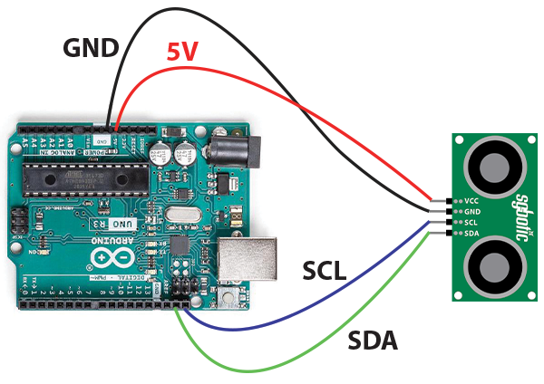
| Arduino Uno | Ultimate SR04 RGB |
| 5V | VCC |
| GND | GND |
| SCL* | SCL |
| SDA* | SDA |
* Both SCL and SDA are located next to the reset button.
The above wiring applies to Ex-1 to Ex-5.
Ex-1: Read Firmware Version
In our first example, we will read the firmware version of the Ultimate SR04 RGB using default I2C address 0x60 (96 in decimal). The result will be printed to a serial monitor.
Function used in this sketch:
uint8_t readVersion(void)
Read the firmware version from the Ultimate SR04 RGB and return the result to user program.
#include "SGBotic_SR04_RGB.h"
#define i2cAddr 0x60  //default i2c address
SGBotic_SR04_RGB sr04_rgb(i2cAddr);
void setup() {
  Serial.begin(9600);
  sr04_rgb.begin();
  Serial.print("firmware version: ");
  Serial.println(sr04_rgb.readVersion());
}
void loop() {
  /** do nothing here **/
}
Ex-2: Blink LED
The sketch will set the light intensity of each colour from low to high, then back to low again.
Functions used in this sketch:
void offAllLED(void)
Turn off all LEDs.
void setLED(uint8_t color, uint8_t brightness)
Set the light intensity of the LED.
- color: Red LED = 1, Green LED = 2, Blue LED = 3
- brightness: 0 to 0xFF (0 = Off, 0xFF = full brightness)
#include "SGBotic_SR04_RGB.h"
#define i2cAddr 0x60  //default i2c address
#define redLED 0x01
#define greenLED 0x02
#define blueLED 0x03
#define light_intensity_min 0x00
#define light_intensity_max 0xff
#define time_delay 10
SGBotic_SR04_RGB sr04_rgb(i2cAddr);
void setup() {
  sr04_rgb.begin();
  //switch off all LEDs
  sr04_rgb.offAllLED();
}
void loop() {
  playLED(redLED);
  playLED(greenLED);
  playLED(blueLED);
}
void playLED(byte led) {
  //from low intensity to high intensity, step of 5
  for (int i = light_intensity_min; i <= light_intensity_max; i = i + 5)
  {
    sr04_rgb.setLED(led, i);
    delay(time_delay);
  }
  //from high intensity to low intensity, step of 5
  for (int i = light_intensity_max; i >= light_intensity_min; i = i - 5)
  {
    sr04_rgb.setLED(led, i);
    delay(time_delay);
  }
}
Ex-3: Measure Distance (Single Unit)
Measure the distance of an object and return the result in centimeters.
Functions used in this sketch:
void trigger(void)
Start measurement.
uint16_t read_cm(void)
Read the result in centimeters.
uint16_t read_us(void)
Read the result in micro-second.
#include "SGBotic_SR04_RGB.h"
#define i2cAddr 0x60  //default i2c address
SGBotic_SR04_RGB sr04_rgb(i2cAddr);
void setup() {
  Serial.begin(9600);
  sr04_rgb.begin();
}
void loop() {
  sr04_rgb.trigger(); // start measurement
  delay(50); //wait for the sensor to acquire data
  Serial.print("cm: ");
  Serial.print(sr04_rgb.read_cm()); // read distance in cm
<span class="redactor-invisible-space">  Serial.print("   us: ");
  Serial.println(sr04_rgb.read_us()); // read distance in uS</span>
  delay(100); // short delay of 0.1 second
}
Ex-4: Measure Distance And Blink LEDs
The sketch measures the distance of an object and changes the color of the LEDs based on the distance measured.
It will turn on BLUE LED If the distance is below 50cm, and RED LED if the distance is higher than 50cm. Take note that the Ultimate SR04 RGB will return 0 if the object is beyond sensing range.
#include "SGBotic_SR04_RGB.h"
#define i2cAddr 0x60  //default i2c address
uint16_t dist_cm, dist_us;
SGBotic_SR04_RGB sr04_rgb(i2cAddr);
void setup() {
  Serial.begin(9600);
  sr04_rgb.begin();
  // read firmware version
  Serial.println(sr04_rgb.readVersion());
  // switch off all LEDs
  sr04_rgb.offAllLED();
}
void loop() {
  // start distance measurement
  sr04_rgb.trigger();
  delay(50); //wait for the sensor to acquire data
  // read distance in cm
  dist_cm = sr04_rgb.read_cm();
  Serial.print("cm: ");
  Serial.println(dist_cm);
  // turn on blue LED if distance measured is less than 50cm
  // The sensor will return 0 if the measurement is beyond sensing range,
  // therefore the valid value should be higher than 0
  if ((dist_cm > 0) && (dist_cm < 50)) {
    sr04_rgb.setLED(blue, 255);
    sr04_rgb.setLED(red, 0);
    // turn on red LED if distance measured is larger than 50cm
  } else {
    sr04_rgb.setLED(blue, 0);
    sr04_rgb.setLED(red, 125);
  }
  delay(100); //delay 0.1s before start next cycle
}
Ex-5: Change I2C Address
The sketch changes the I2C address. Once the I2C address is successfully changed, the LED on the transducers will blink 4 times. The new address will be permanently stored until next request occurs.
For the Ultimate SR04 RGB to run on new I2C address, reset the sensor by remove and re-connect the power.
Refer to the User Guide on resetting the I2C address to default value.
Function used in this sketch:
void setI2CAddress(uint8_t newAddr)
The valid value of the target address (newAddr) is from 0x08 to 0x71.
#include "SGBotic_SR04_RGB.h"
#define existing_addr 0x60
#define new_addr 0x61  //valid I2C address: 0x08 to 0x71
SGBotic_SR04_RGB sr04_rgb(existing_addr);
void setup() {
  sr04_rgb.begin();
  sr04_rgb.setI2CAddress(new_addr);
}
void loop() {
  /***  do nothing;  ***/
}
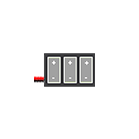
Ex-6: Measure Distance (Three Units)
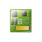
Wiring:
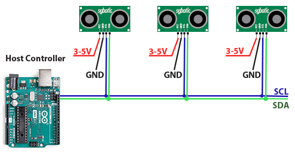
Code:
This example uses three Ultimate SR04 RGB for distance measurement. All units must configure to different addresses before connecting to I2C bus.
The sketch triggers the three units in sequence, delay for 50 mS and return to read back the results. The results will be printed to a serial monitor.
#include "SGBotic_SR04_RGB.h"
#define i2cAddr01 0x59  //i2c address of first sensor
#define i2cAddr02 0x60  //i2c address of second sensor
#define i2cAddr03 0x61  //i2c address of third sensor
SGBotic_SR04_RGB sr04_rgb_01(i2cAddr01); // initialize ultrasonic sensor
SGBotic_SR04_RGB sr04_rgb_02(i2cAddr02);
SGBotic_SR04_RGB sr04_rgb_03(i2cAddr03);
void setup() {
  Serial.begin(9600);
  sr04_rgb_01.begin();
  sr04_rgb_02.begin();
  sr04_rgb_03.begin();
}
void loop() {
  sr04_rgb_01.trigger(); // start measurement of sensor #1
  sr04_rgb_02.trigger(); // start measurement of sensor #2
  sr04_rgb_03.trigger(); // start measurement of sensor #3
  delay(50); //wait for the sensor to acquire data
  Serial.print("#1: ");
  Serial.print(sr04_rgb_01.read_cm()); // read sensor #1distance in cm
  Serial.print("   #2: ");
  Serial.print(sr04_rgb_02.read_cm()); // read sensor #2 distance in cm
  Serial.print("   #3: ");
  Serial.println(sr04_rgb_03.read_cm()); // read sensor #3 distance in cm
  //delay(100); // short delay of 0.1 second
}
