


SGBotic Ultimate SR04 RGB Ultrasonic Sensor - User Guide
SGBotic Ultimate SR04 RGB Ultrasonic Sensor uses dedicated microcontroller for I2C interface, RGB control and ultrasonic ranging. Although this sensor is based on the design of the popular HC-SR04, its operation and interfacing are completely different.
This user guide will walk you through the technical aspect of the sensor. We have written a library / extensions and example codes for Arduino board and Micro:bit. If you're using these controller boards, you can head over to the respective tutorial.
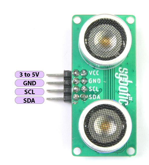
Pinout
The Ultimate SR04 RGB uses I2C interface to send and receive data. Only two data pins are required to connect single or multiple units of this sensor to the host controller.
I2C Registers
The Ultimate SR04 RGB has 10 registers in total.
| Register | Action | Read/Write | Value |
| 0x01 | Start measurement | W | 0x01 |
| 0x02 | Light intensity - Red | W | 0 to 0xFF |
| 0x03 | Light intensity - Green | W | 0 to 0xFF |
| 0x04 | Light intensity - Blue | W | 0 to 0xFF |
| 0x0A | Result in centimeters | R | MSB |
| 0x0B | Result in centimeters | R | LSB |
| 0x0C | Result in micro-seconds | R | MSB |
| 0x0D | Result in micro-seconds | R | LSB |
| 0xE0 | Set I2C address | W | 0x08 to 0x71 |
| 0xF0 | Read firmware version | R | 0x01 to 0xFF |
The sensor will start measurement upon writing 0x01 to register 0x01. Once the results are ready, it will store them in registers 0x0A to 0x0D where 0x0A and 0x0B are in centimeters and 0x0C and 0x0D are in micro-seconds.
Writing 0x00~0xFF to registers 0x02, 0x03 and 0x04 will set the light intensity of the embedded Red, Green and Blue LED respectively.
The I2C address can be set by writing valid value to register 0xE0. The command will be ignored if the value sent is outside the range from 0x08 to 0x71.
Reading from register 0xF0 will return the firmware version.
RGB Illuminate Transducers
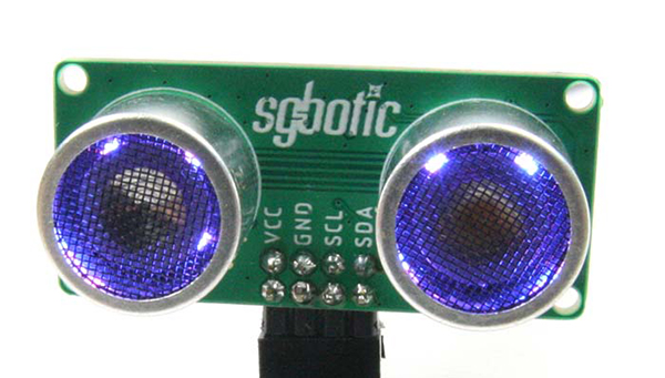
The transducers used in the Ultimate SR04 RGB are embellished with RGB LEDs. The light intensity of the colours can be individually controlled by user program. The value ranges from 0 to 255 (0xFF in hexadecimal) where 0 will turn off the LED and 255 in full brightness.
Higher light intensity will consume higher current. Therefore if you are operating on non-rechargeable batteries such as alkaline batteries, you may want to tune down the brightness to extend the lifespan of your batteries.
Configure I2C Address
The I2C address of the Ultimate SR04 RGB can be changed by writing the target I2C address to register 0xE0. Once the I2C address is successfully written, the LEDs in the transducers will blink 4 times. The new address will be permanently stored until the next request occurs.
The range of a valid I2C address is from 8 to 113 (0x08 to 0x71 in hexadecimal). The firmware will ignore the command if the value sent is outside the range.
For the sensor to run on new I2C address, reset it by power cycle the sensor (i.e. remove and re-connect the power).
Reset I2C Address To Factory Setting
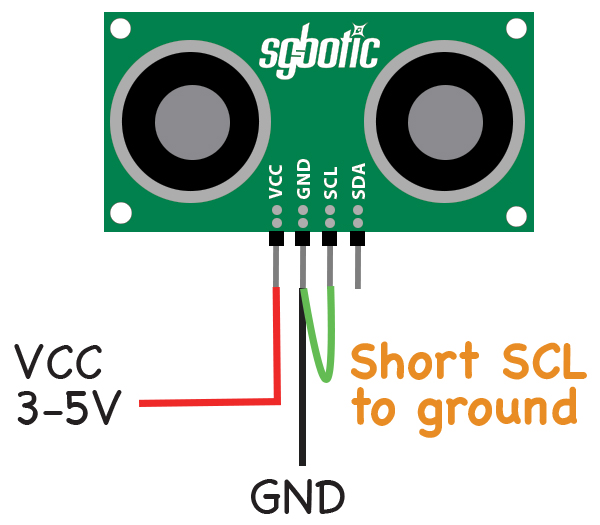
To reset the I2C address to factory setting,
- short the SCL pin to ground
- apply 3~5V to VCC pin.
The green LED in the transducers will blink 3 times when the reset is completed. The I2C address is now reset back to 96 (0x60 in hexadecimal). Power cycle the sensor for the change to take effect.
Connecting Multiple Units To I2C Bus
All the Ultimate SR04 RGB that you intend to connect to I2C bus must have unique I2C address. The valid I2C address is from 8 to 113 (0x08 to 0x71 in hexadecimal).
The wiring, as shown in the diagram below, is quite straight forward:
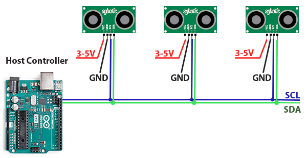
Check out the section below on the pull-up resistors and bus impedances that may cause signal lost if you are using a longer cable or are placing the units far apart.
I2C Pull-up Resistors and Impedance Matching
Both the SCL and SDA are pull-up to 3.3V through a 4.7K resistor (R13 and R14). The resistors are located next to the male pin headers.
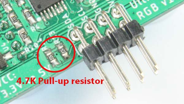
Depending on the type of cable (twisted / non-twisted, AWG, etc), length of cable and the distance between the units, you may need to remove these resistors or change to other value to prevent signal lost due to impedance mismatch. The pull-up resistors may not have significant impact on the bus impedance if the sensors are placed in close proximity.
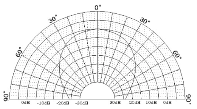
Beam Pattern and Beam Width
The ultrasonic transducers used in the Ultimate SR04 RGB operates at 40KHz and has a beam width of 60 degree at -6dB.
The beam width is fixed and cannot be changed by software. The beam pattern of the transducers used (taken from the manufacturer data sheet) is shown below:
Temperature Compensation
The Ultimate SR04 RGB calculates the distance of the object from the speed of sound. The speed of sound is temperature-dependent. Higher temperature will cause sound wave to travel faster while opposite is true for lower temperature. Therefore, as the temperature increases, sound wave will travel faster to and from the object, and it will appear to the sensor that the object is closer even though the object has not shifted.
The speed of sound will change by approximately 0.6m/s with each degree celsius.
The firmware of the Ultimate SR04 RGB uses sound speed of 345m/s (Ambient temperature of approx. 23 degC) to calculate the distance. If you want to apply temperature compensation in your program, you may apply the following simplified formula to the read distance measured in micro-second:
distance in cm = (331.3 + (0.606 * temperature) ) * distance in micro-second
