


Access Barrier Kit User Guide
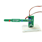
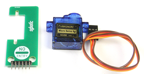
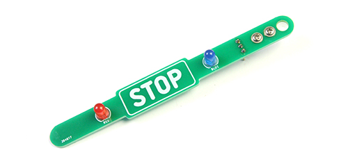
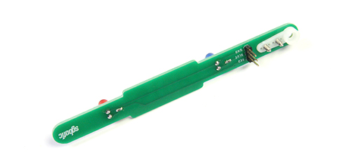
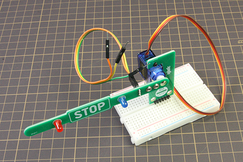
The Access Barrier Kit uses a servo motor to lift up/down the barrier bar and is programmable using an Arduino microcontroller or BBC Micro:bit. The bar has two LEDs (Red and Blue) which can be individually controlled. The kit is designed to plug into a breadboard.
In the guide below we will walk you through the steps to assemble this Access Barrier Kit and to control the barrier bar and LEDs using Arduino and Micro:bit.
The sample code used in this guide is available here.
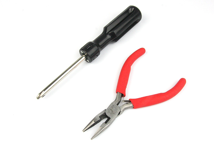
Recommended Tools
Small philips head screwdriver and plier.
Assembly Guide
Attach the servo motor to the base plate
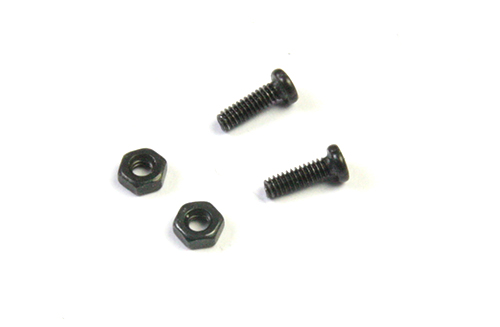
Secure the servo motor to the base plate using two M2 screws and nuts.
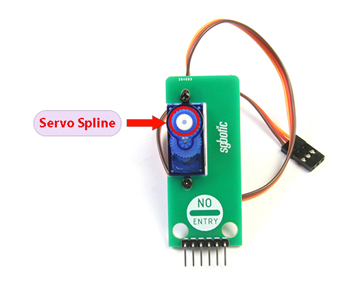
Place the servo in the manner as shown below, with the servo spline closer to the top edge of the base plate:
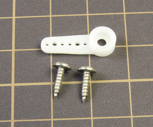
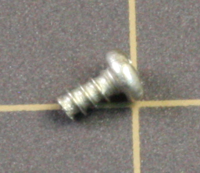
Attach the servo horn to the barrier bar
Attach the servo horn to the barrier bar using two self-tapping screws.
Set the Servo Spline to home position
Before attaching the barrier bar to the servo motor, we need to set the servo spline to home position. In this setup, we will set the spline angle to 100 degrees.
Using Arduino Board
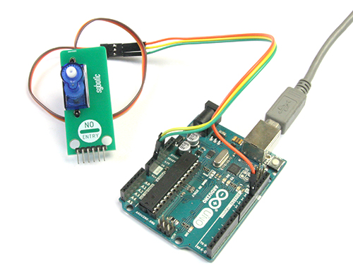
Connect the servo motor to the Arduino board. Depending on the type of Arduino board you are using, you may need additional jumper wires to match the connector on your Arduino board.
| Servo Motor | Arduino |
| Orange wire | pin 12 |
| Red wire | 5V |
| Brown wire | GND |
Install the servo library to your Arduino IDE. For instruction on how to install the library, you may refer to this link: https://www.arduino.cc/en/Guide/Libraries
Create the sketch and upload it to your Arduino board:
  /************************************************************************
     File: access_barrier_set_home_pos.ino
     This sketch move the servo spline to home position
   ***********************************************************************/
#include <Servo.h>

int servoPin = 12;
int homePos = 100;

Servo myservo;  // create servo object to control a servo

void setup() {
  myservo.attach(servoPin);  // attaches the servo on pin 12 to the servo object
  myservo.write(homePos);   // move servo spline to home position
}

void loop() {
 //do nothing
}
Once your program is executed, the servo spline should rotate to 100 degree.
Using BBC Micro:bit
Note: The servo motor can be driven directly by Micro:bit version 2, but not version 1.
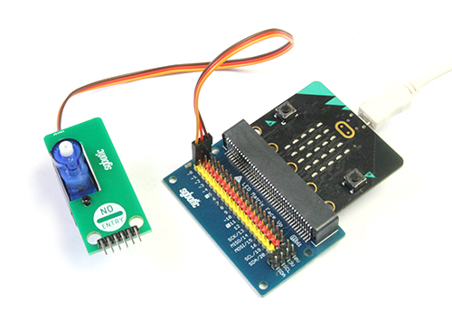
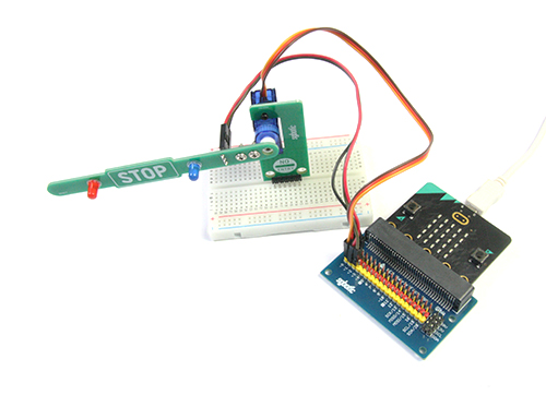
Connect the servo motor to the Micro:bit interface board. Depending on the type of board you are using, you may need additional jumper wires to match the connector on your interface board.
| Servo Motor | Micro:bit |
| Orange wire | pin 0 |
| Red wire | 3V |
| Brown wire | 0V |
Create the code and upload it to your micro:bit:
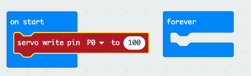
Once your program is executed, the servo spline should rotate to 100 degree.
Attach the barrier bar to servo motor
After you have set the servo spline to home position, you can now proceed to attach the barrier bar to the servo motor. Use M2 self tapping screw to secure the barrier bar.
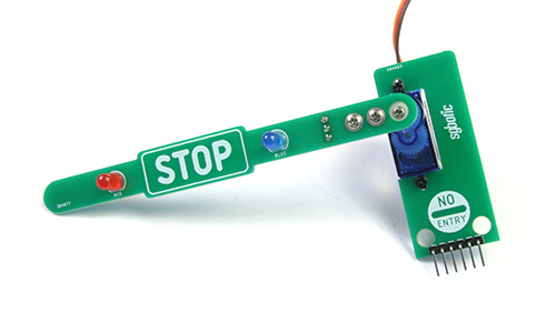
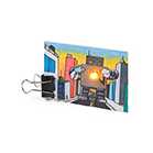
Final Assembly
To complete the assembly, connect the jumper wires to the LED pins and mount the assembled kit to a breadboard.
Example code
In the examples below, we will show you how to control the Access Barrier Kit using Arduino and Micro:bit.
Using Arduino Board
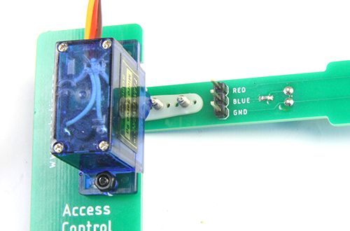
We will continue to use pin 12 to control the servo motor. For LED connection, refer to the table below:
| Barrier bar's LED pins | Arduino Board |
| Red | 11 |
| Blue | 10 |
| GND | GND |
The Access Barrier Kit comes with female to female jumper wire for connecting the LEDs to the controller. To match the connector on your Arduino board, you may need additional jumper wires.
Create the sketch and upload it to your Arduino board, The barrier bar will raise for 5 seconds and lower for 5 seconds, and will repeat until the power is cut-off.
 /************************************************************************
     File: access_barrier_example.ino
     This sketch raise and lower the barrier bar and control the LEDs according
     to barrier bar position.
   ***********************************************************************/
#include <Servo.h>

int servoPin = 12;  // pin connect to servo motor
int dwnPos = 100;   // angle of spline when barrier bar is lifted down
int upPos = 0;      // angle of spline when barrier bar is lifted up
int pinRed = 11;    // pin connect to red LED
int pinBlue = 10;   // pin connect to blue LED

Servo myservo;  // create servo object to control a servo

void setup() {
  pinMode(pinRed, OUTPUT);  // intialize digital pin 11 as output.
  pinMode(pinBlue, OUTPUT); // initialize digital pin 10 as output.
  myservo.attach(servoPin); // attaches the servo on pin 12 to the servo object
  myservo.write(dwnPos);    // lower the barrier bar
}

void loop() {
  barrierUp();  // raise the barrier bar
  delay(5000);  // delay 5 seconds
  barrierDwn(); // lower the barrier bar
  delay(5000);  // delay 5 seconds
}

void barrierUp() {
  digitalWrite(pinRed, HIGH);   // turn the red LED off
  digitalWrite(pinBlue, HIGH);  // turn the blue LED off
  myservo.write(dwnPos);       // lower the barrier bar
}

void barrierDwn() {
  digitalWrite(pinRed, LOW);   // turn the red LED on
  digitalWrite(pinBlue, LOW);  // turn the blue LED on
  myservo.write(upPos);       // raise the barrier bar
}
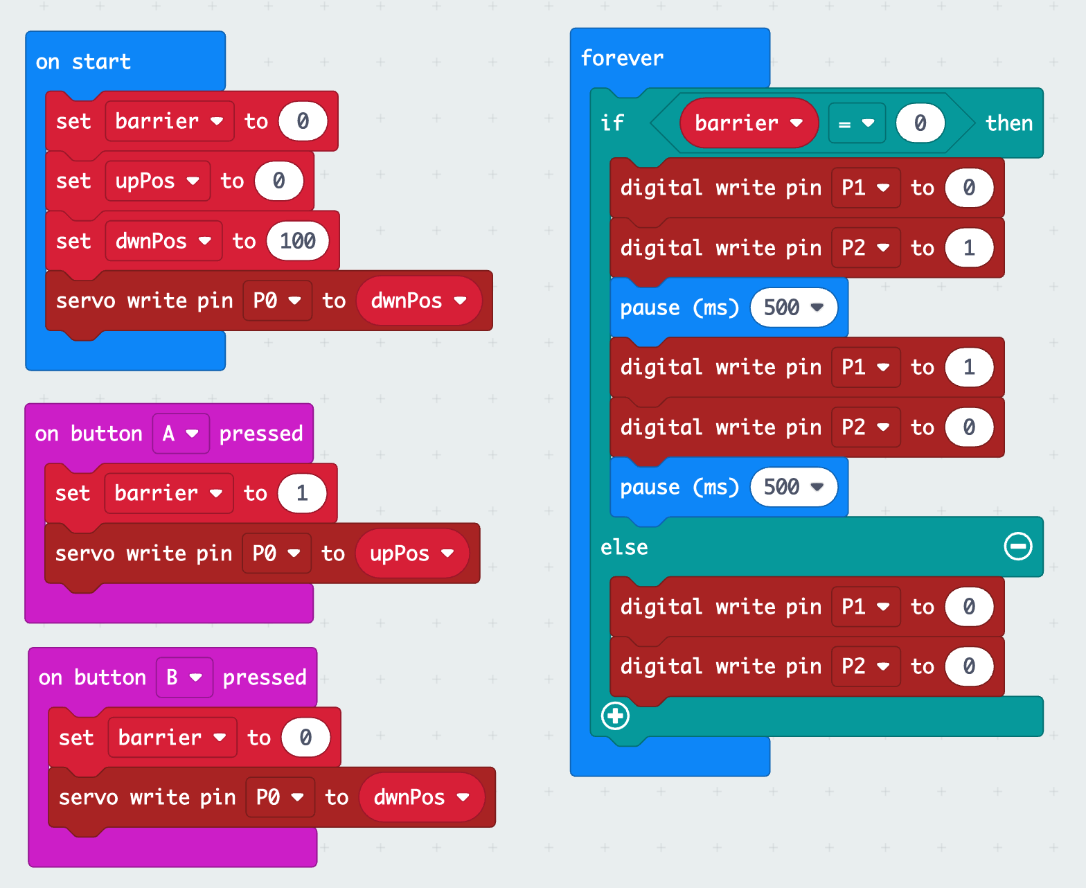
Using Micro:bit
We will continue to use pin 0 to control the servo motor. For LED connection, refer to the table below:
| Barrier bar's LED pins | Micro:bit |
| Red | pin 1 |
| Blue | pin 2 |
| GND | 0V |
The Access Barrier Kit comes with female to female jumper wire, you may need additional jumper wires to match the connector on your interface board.
Create the code and upload it to your Micro:bit. Press button A to raise the barrier bar and button B to lower. The LEDs will blink when the barrier bar is lowered and off when the barrier bar is raised.